
Bill MaschinotIndependent consultant
A single-tube Coriolis flow meter is a cylindrical device that’s mounted inline on a tablet coating system’s solution supply tube. The flow meter monitors the coating solution flowrate and directly or indirectly sends the data to the coating pump controller, which continuously adjusts the pump speed (rpm) to maintain the required flowrate.
As coating solution flows through the meter, it generates friction, which causes the tube inside the flow meter to vibrate and twist. This vibration varies in frequency depending on the speed of the solution flowing through the meter and the solution’s characteristics. A sensor inside the meter measures this frequency and uses the measurement to calculate the solution’s flowrate, either by converting density to a mass flowrate or by using multiple variables such as temperature, pressure, viscosity, density, and percentage of solids to calculate a volumetric flowrate.
I have yet to work with a process engineer, development scientist, or technician who truly understands the function of a single-tube Coriolis flow meter well enough to troubleshoot flow system issues. This knowledge gap often leads to poorly validated flow systems that technicians and operators are left to deal with on a daily basis. I often wonder how many unrelated mistakes frustrated technicians or operators have made because they were sidetracked by improperly functioning flow systems. To circumvent this lack of knowledge about flow-meter function, many companies opt to run their flow meters in mass mode, claiming that their tablets are coated using the weight-gain method, so flowrate isn’t critical. This statement could not be further from the truth and is not a valid justification.
For example, if you have your flow meter operating in mass mode but haven’t re-zeroed the meter recently, the system may not actually be delivering the desired flowrate. This will impact the solution’s atomization, spray pattern, and droplet size, all of which directly affect tablet appearance. Excess flow can cause over-wetting of the tablets, which contributes to problems such as twinning, picking, sticking, and erosion. Some of this excess solution goes directly to the dust collector, which creates buildup in the ductwork, prematurely blinds the dust collector filters, and increases downtime and maintenance costs due to more frequent ductwork cleaning and filter and waste drum changes. Also, to make up for the wasted solution, you may need to increase the coating solution batch size by 20 to 40 percent to avoid running out of solution before the tablets reach the desired weight.
If your actual flowrate is lower than the desired flowrate, on the other hand, the solution may atomize too quickly, and the droplets will dry before reaching the tablets. The solution droplets must contain enough moisture at the time of impact to adhere to the tablet surface, otherwise the dry particles will bounce off the tablets and be carried away in the exhaust airstream to the dust collector. This also wastes coating solution.
Both of these scenarios are preventable if you understand how your equipment operates. Volumetric flowrate is a more appropriate form of measurement than mass flowrate for the pharmaceutical industry because it accounts for the constant changes your solution is subjected to as well as any environmental changes occurring during the coating process. For volumetric flowrate, a single-tube Coriolis flow meter uses the solution’s temperature, pressure, viscosity, density, and percentage of solids to accurately calculate flowrate. As a result, if the flow meter is set up properly and re-zeroed after being primed with your solution, volumetric flowrate measurements are more accurate than mass flowrate measurements by approximately 0.1 percent, though this rating may vary depending on the flow meter manufacturer.
The pharmaceutical companies I’ve worked for have often had unidentifiable long-term coating solution flowrate issues. One company even worked around these issues by consistently performing flowrate checks before each batch until one of the checks passed. If the company couldn’t get a passing result, the metrology department would recalibrate the flow meter using water. Recalibrating a single-tube Coriolis flow meter with water requires that the meter be cleaned so that metrology can install dedicated calibration instruments, re-zero the meter, and perform a flowrate check. While recalibrating the flow meter will almost always result in a passing flowrate check and get the coating system back in operation, it’s a time-consuming process that leaves the company behind schedule.
Solution Delivery System Setup
Over the years, I’ve been asked to troubleshoot many coating solution delivery systems and have developed a procedure for optimizing system setup and single-tube Coriolis flow meter performance. Note that, while this information primarily concerns flow meters being used with tablet coating systems, the principles are nearly identical for any process—such as spray granulation— that uses a single-tube Coriolis flow meter.
A coating solution delivery system typically consists of a coating solution tank, a solution supply tube, a peristaltic pump, an automated shut-off valve, a singletube Coriolis flow meter, a manifold, and several spray guns. It’s important that the coating solution tank’s discharge be located at the bottom of the tank. Since the peristaltic pump performs most of its work getting the solution from the tank to the pump, more head pressure in the tank—along with as large a supply-tube diameter and as short a distance between the tank and the pump as possible—means less work for the pump. A ball valve is typically attached to the tank discharge, and the solution supply tube is attached to the ball valve. I recommend using braided hose for the supply tube to limit the pulsing effect created by the peristaltic pump.
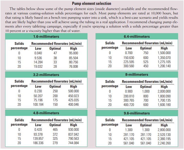
The other end of the supply tube attaches to a barbed fitting on the end of the peristaltic pump element. Most peristaltic pump elements use special tubing designed to handle millions of compression cycles from the pump’s rollers during operation. Unlike most tubing, peristaltic pump elements are designed to quickly regain their shape after each pass of the roller. The peristaltic action of the rollers against the pump elements is what moves the coating solution through the supply tube, but it also causes additional frequencies to pass through the solution to the flow meter. If these frequencies are irregular and inconsistent, they can impact the flow meter’s measurements or even cause the meter’s zero point to drift.
To minimize these additional frequencies, I recommend using a double peristaltic pump. Instead of having a single tube element passing through the pump, a double peristaltic pump has a double tube element. A barbed Y fitting splits the single supply tube coming from the tank into two separate tube elements that pass through the pump. The double tube peristaltic pump has a specially designed cover that fits over the rollers to create an engineered offset that prevents the pump from cycling both tubes simultaneously. This offset minimizes the frequency fluctuations generated by the pump and keeps the flow meter readings more consistent. At the exit of the peristaltic pump, another barbed Y fitting merges the pump’s two tube elements back into a single supply tube. I recommend Watson-Marlow double peristaltic pumps, which are widely used, and double Gore Sta-Pure tubing elements. (Note that using Sta-Pure tubing elements with a Watson-Marlow 505L pump head requires that you use a different spring setup, called a 505-LG.)
It’s important to have a preventative maintenance plan in place to keep your pump in top condition. You should regularly check the pump head and rollers for play, which can impact flowrate accuracy. With the unit locked out, you shouldn’t be able to rotate the pump head in either direction. Check each individual roller for play and free movement. The rollers should spin freely but shouldn’t have play in any direction (up, down, left, right, in, and out). Any play will impact your flowrate, and continuing to run a pump that has play in it will ultimately damage the pump’s gearbox. The pump continually adjusts its speed to maintain the desired flowrate based on feedback from the flow meter. Usually, these speed adjustments are so minimal that they’re hard to detect by looking at the pump. However, if there is any play in the pump, these minor adjustments can create inconsistencies in the vibration frequencies read by the flow meter and cause the meter’s zero point to drift.
From the peristaltic pump, the coating solution supply hose first goes to an automated shut-off valve that opens and closes as the spray system is turned on and off and then continues on to the flow meter.
Mounting the Flow Meter
Mounting the flow meter is critical because any disturbances to the outside of the meter can cause flowrate fluctuations. Something as simple as bumping the hose at the top of the flow meter during operation can cause the meter’s zero setting to drift, leading to flowrate errors.
In nearly every installation I’ve seen, the flow meter is mounted using a bracket around each end, just before the sanitary fitting, as shown in Photo 1. However, this mounting method can choke the flow meter and cause the zero setting to drift. To prevent this, the flow meter should be suspended with nothing touching it but two tri-clover clamps, one at each end. To achieve this suspension but still have the flow meter mounted securely, attach six-inch straight sanitary tubes to the meter’s inlet and outlet sides using tri-clover clamps. This isolates the flow meter and prevents it from binding. This also provides six inches of straight tubing both before and after the flow meter, which is recommended by most manufacturers to prevent or limit turbulence at the meter’s sensor.
The six-inch tubes also serve as installation points for the flow meter’s mounting brackets. Each tube should be secured in place with a top and bottom bracket, as shown in Figure 1. This ensures that the flow meter is securely mounted and prevents twisting. You can also install a ball valve at the end of each of these six-inch tubes, so you can easily isolate the flow meter for re-zeroing. The rest of the set u p typically involves installing the manifold, which splits the supply tube into multiple branches to feed the coater’s spray guns. The details of this part of the setup aren’t critical to the function of the flow meter, but you should be sure to follow the coater manufacturer’s instructions to complete the setup process.
Once the entire coating system is set up, filled, and ready to spray, you should re-zero the flow meter. You should also re-zero the meter before each batch because of all the external influences that could affect the flow meter any time a new batch is started. This is more difficult if your flow meter doesn’t have an externally mounted transmitter, but it’s important nonetheless and should be performed prior to every batch.
Bill Maschinot is an independent consultant who has held a variety of positions at several pharmaceutical companies, primarily in manufacturing solid dosage forms as a Six Sigma black belt, process engineer, process scientist, equipment maintenance engineer, and manufacturing manager. You can contact him with questions about this article or for further equipment recommendations based on your specific scenario at 937 545 9821 or maschinot@gmail.com.